LCD modules find applications in various electronic projects and devices where visual information needs to be presented. They offer clear and readable displays, making them suitable for a range of applications including consumer electronics, industrial control panels, automotive displays, measurement devices, and many other systems that require visual output and user interaction.
The characters displayed on the LCD module are formed using a 5x7 pixel matrix. This means that each character is constructed using a grid of 5 pixels in width and 7 pixels in height.
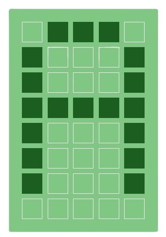
By activating or deactivating the individual pixels within the matrix, different characters can be displayed on the screen.
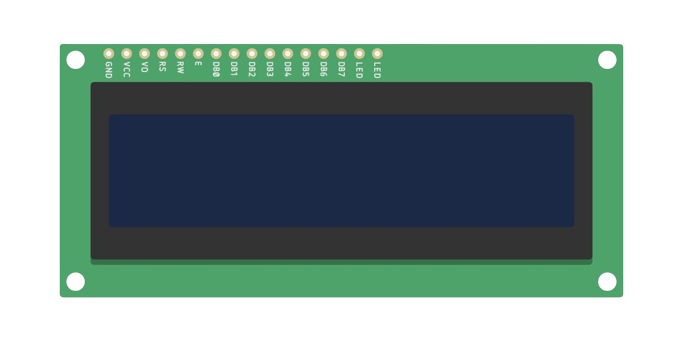
The LCD 16x2 module is commonly used in various electronic projects and devices. It provides a simple and compact way to present information or messages in a clear and readable format.
liquid crystal display (Hitachi HD44780U based LCD )
Simple Instructions Set
The instruction set for a liquid crystal display (LCD) depends on the specific controller or driver used with the LCD module. The most common controller used in LCD modules is the Hitachi HD44780U, which has a widely adopted instruction set.
Instruction Set
| Instruction
|
Code
|
Description
|
| RS
|
R/W
|
B7
|
B6
|
B5
|
B4
|
B3
|
B2
|
B1
|
B0
|
| Clear display
|
0
|
0
|
0
|
0
|
0
|
0
|
0
|
0
|
0
|
1
|
Clears display and returns cursor to the home position (address 0).
|
| Cursor home
|
0
|
0
|
0
|
0
|
0
|
0
|
0
|
0
|
1
|
*
|
Returns cursor to home position. Also returns display being shifted to the original position. DDRAM content remains unchanged.
|
| Entry mode set
|
0
|
0
|
0
|
0
|
0
|
0
|
0
|
1
|
I/D
|
S
|
Sets cursor move direction (I/D); specifies to shift the display (S). These operations are performed during data read/write.
|
| Display on/off control
|
0
|
0
|
0
|
0
|
0
|
0
|
1
|
D
|
C
|
B
|
Sets on/off of all display (D), cursor on/off (C), and blink of cursor position character (B).
|
| Cursor/display shift
|
0
|
0
|
0
|
0
|
0
|
1
|
S/C
|
R/L
|
*
|
*
|
Sets cursor-move or display-shift (S/C), shift direction (R/L). DDRAM content remains unchanged.
|
| Function set
|
0
|
0
|
0
|
0
|
1
|
DL
|
N
|
F
|
*
|
*
|
Sets interface data length (DL), number of display line (N), and character font (F).
|
Read busy flag &
address counter
|
0
|
1
|
BF
|
CGRAM/DDRAM address
|
Reads busy flag (BF) indicating internal operation being performed and reads CGRAM or DDRAM address counter contents (depending on previous instruction).
|
Write CGRAM or
DDRAM
|
1
|
0
|
Write Data
|
Write data to CGRAM or DDRAM.
|
Write CGRAM or
DDRAM
|
1
|
0
|
Write Data
|
Write data to CGRAM or DDRAM.
|
Instruction bit names
I/D - 0 = decrement cursor position, 1 = increment cursor position;
S - 0 = no display shift, 1 = display shift;
D - 0 = display off, 1 = display on;
C - 0 = cursor off, 1 = cursor on;
B - 0 = cursor blink off, 1 = cursor blink on
S/C - 0 = move cursor, 1 = shift display
R/L - 0 = shift left, 1 = shift right
DL - 0 = 4-bit interface, 1 = 8-bit interface
N - 0 = 1/8 or 1/11 duty (1 line), 1 = 1/16 duty (2 lines)
F - 0 = 5×8 dots, 1 = 5×10 dots
BF - 0 = can accept instruction, 1 = internal operation in progress.
Hitachi HD44780U Based LCD
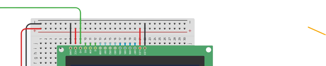
Pins Description
It's important to note that the specific pin configuration and assignment may vary based on the LCD module and controller used.
VSS (Ground)
This pin is connected to the ground reference of the system.
VDD (VCC)
This pin is connected to the power supply voltage, typically +5V.
VEE (Contrast Voltage)
This pin is used to adjust the contrast of the display. By varying the voltage applied to this pin, the contrast level of the characters can be adjusted.
RS (Register Select)
This pin determines whether the data being sent to the LCD is a command or character data. When RS is set to logic low (0), the data is treated as a command. When RS is set to logic high (1), the data is treated as character data.
R/W (Read/Write)
This pin determines the direction of data transfer. When R/W is set to logic low (0), data is written to the LCD module. When R/W is set to logic high (1), data is read from the LCD module.
E (Enable)
This pin is used to enable the LCD module for data transfer. A falling edge trigger is required to latch the data present on the data bus. Data is latched into the LCD module when the E pin transitions from high to low.
D0-D7 (Data Lines)
These pins are used for bidirectional data transfer between the microcontroller and the LCD module. In 8-bit mode, all eight data lines (D0-D7) are used for communication. In 4-bit mode, only the four higher-order data lines (D4-D7) are used, and the four lower-order data lines (D0-D3) are not connected.
A (Anode) or LED+ (Backlight Anode)
This pin is used to connect the positive terminal of the backlight. Applying voltage to this pin turns on the backlight and provides illumination to the display.
K (Cathode) or LED- (Backlight Cathode)
This pin is used to connect the negative terminal of the backlight. Grounding this pin completes the backlight circuit.
Pin Descriptions
| PIN NUMBER |
FUNCTION |
| 1 |
Ground |
| 2 |
VCC |
| 3 |
Contrast adjustment (VO) |
| 4 |
Register Select (RS). RS=0: Command, RS=1: Data |
| 5 |
Read/Write (R/W). R/W=0: Write, R/W=1: Read |
| 6 |
Clock (Enable). Falling edge triggered |
| 7 |
Bit 0 (Not used in 4-bit operation) |
| 8 |
Bit 1 (Not used in 4-bit operation) |
| 9 |
Bit 2 (Not used in 4-bit operation) |
| 10 |
Bit 3 (Not used in 4-bit operation) |
| 11 |
Bit 4 |
| 12 |
Bit 5 |
| 13 |
Bit 6 |
| 14 |
Bit 7 |
| 15 |
Back-light Anode(+) |
| 16 |
Back-Light Cathode(-) |