The ATmega8 microcontroller has three ports: PORTB, PORTC, and PORTD. Each of these ports has three 8-bit registers associated with it: DDRx, PORTx, and PINx, where x is the port letter (B, C, or D).
Each of these registers is 8 bits wide, corresponding to the 8 pins on each port. The bits are usually labeled as 7 to 0 or 0 to 7, depending on the specific datasheet or reference material.
| DDxn |
PORTxn |
PUD (in SFIOR) |
I/O |
Pull-up |
Comment |
| 0 |
0 |
X |
Input |
No |
Tri-state (Hi-Z) |
| 0 |
1 |
0 |
Input |
Yes |
Pxn will source current if external pulled low. |
| 0 |
1 |
1 |
Input |
No |
Tri-state (Hi-Z) |
| 1 |
0 |
X |
Output |
No |
Output Low (Sink) |
| 1 |
1 |
X |
Output |
No |
Output High (Source) |
To access and control the GPIO pins on the ATmega8, a programmer can use various programming languages such as C, C++, and assembly language. We can use different development tools such as AVR Studio, Mplabx, or Arduino IDE to write code and compile.
The code can be written to configure the pins as inputs or outputs, set the output voltage, and read the input voltage.
The ability to configure each pin as an input or output, and to set or read the logic level on each pin, makes the ATmega8 a versatile microcontroller for many different types of projects.
DDRx (Data Direction Register)
This register is used to configure the direction (Input or Output) of the I/O pins. If a bit in the DDRx is written logic one, the corresponding port pin is configured as an output pin.
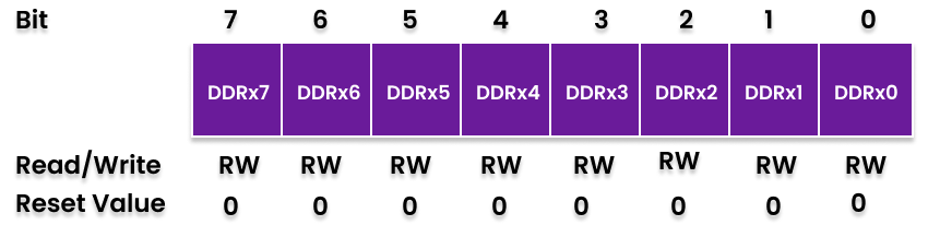 If a bit in the DDRx register is written logic zero, the corresponding port pin is configured as an input pin.
PORTx (Data Register)
If the port is configured as an output, the PORTx register contains the output level (High/Low) of the I/O pins.
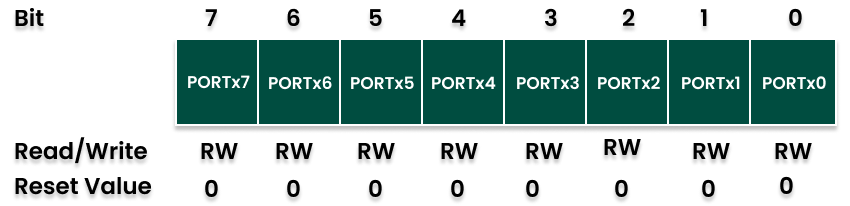 If the port is configured as an input, the PORTx register bit defines the function of the pin as a pull-up resistor.
PINx (Pin Input Register)
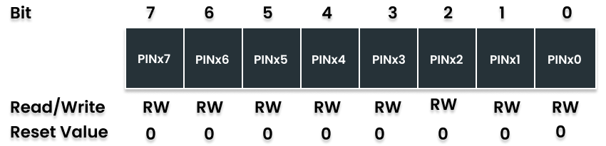 This register is used to read the logic level present at the I/O pins.
settings_accessibility
The GPIOs on the ATmega8 microcontroller provide a flexible and powerful way to interface with other digital circuits and devices. By configuring the pins as inputs or outputs and writing appropriate code, a wide variety of applications can be built using this microcontroller.
For example, the following code configures PORTB pin 0 as an output and sets the voltage to high
    // set PB0 as output
    DDRB |= (1 << PB0);

    // set PB0 voltage high
    PORTB |= (1 << PB0);