timer

ATmega8 Timer 0


Timer 0 in the ATmega8 microcontroller is a fundamental tool for those diving into the world of embedded systems. As one of the three timers available in this popular AVR family microcontroller, understanding Timer 0 is crucial for a plethora of applications.

update Timer 0 in the ATmega8 is an 8-bit timer, meaning it can count from 0 to 255. Once it reaches its maximum value, it overflows and starts again from zero. This simple yet powerful tool allows developers to create precise time intervals and delays in their applications.

The counting direction is always up (incrementing), and no counter-clear is performed. The counter simply overruns when it passes its maximum 8-bit value (MAX = 0xFF) and then restarts from the bottom (0x00).

In normal operation, the Timer/Counter Overflow Flag (TOV0) will be set in the same timer clock cycle as the TCNT0 becomes zero. The TOV0 Flag in this case behaves like a ninth bit, except that it is only set, not cleared.

However, combined with the timer overflow interrupt that automatically clears the TOV0 Flag, the timer resolution can be increased by software. A new counter value can be written anytime.

A simplified block diagram of the 8-bit Timer/Counter

The Timer/Counter can be clocked internally or via the prescaler, or by an external clock source on the T0 pin. The Clock Select logic block controls which clock source and edge the Timer/Counter uses to increment its value. The Timer/Counter is inactive when no clock source is selected. The output from the clock select logic is referred to as the timer clock (clkT0).

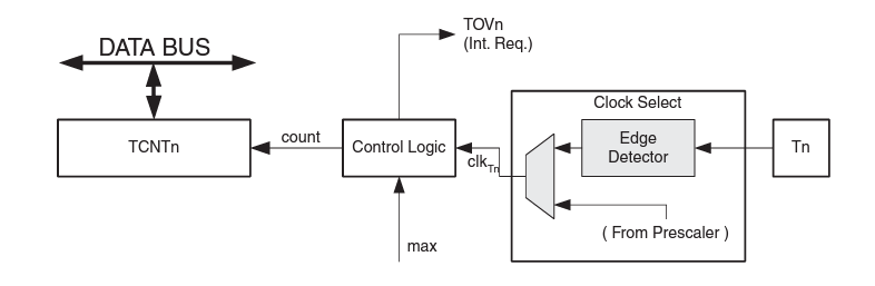
Timer/Counter Unit Block Diagram

The Timer/Counter can be clocked by an internal or an external clock source. The clock source is selected by the clock select logic which is controlled by the clock select (CS02:0) bits located in the Timer/Counter Control Register (TCCR0).

Key Registers

  • TCCR0 (Timer/Counter Control Register 0)

    BIT 7BIT 6BIT 5BIT 4BIT 3BIT 2BIT 1BIT 0
    -----CS02CS01CS00

    This register is used to configure the Timer 0 prescaler value.

    CS02 CS01 CS00 Description
    0 0 0 No clock source (Timer/Counter stopped)
    0 0 1 clkI/O/(No prescaling)
    0 1 0 clkI/O/8 (From prescaler)
    0 1 1 clkI/O/64 (From prescaler)
    1 0 0 clkI/O/256 (From prescaler)
    1 0 1 clkI/O/1024 (From prescaler)
    1 1 0 External clock source on T0 pin. Clock on falling edge
    1 1 1 External clock source on T0 pin. Clock on rising edge
  • TCNT0 (Timer/Counter 0)

    This 8-bit register holds the current count value of Timer 0.

  • TIMSK (Timer/Counter Interrupt Mask Register)

    This register contains bits that enable or disable Timer 0 related interrupts.

    BIT7 BIT6 BIT5 BIT4 BIT3 BIT2 BIT1 BIT0
    OCIE2 TOIE2 TICIE1 OCIE1A OCIE1B TOIE1 - TOIE0

    Bit 0 – TOIE0: Timer/Counter0 Overflow Interrupt Enable

    When the TOIE0 bit is written to one, and the I-bit in the Status Register(Global Interrupt Enabled using 'sei()' ) is set (one) , the Timer/Counter0 Overflow interrupt is enabled.

    The corresponding interrupt is executed if an overflow in Timer/Counter0 occurs, that is, when the TOV0 bit is set in the Timer/Counter Interrupt Flag Register – TIFR.

    In Atmega8 and other AVR microcontrollers, the sei() function stands for "Set Interrupt". When used in an AVR program, it sets (enables) the Global Interrupt Enable (I) flag in the Status Register (SREG).

    When the Global Interrupt Enable bit is set, any interrupt source with its individual interrupt enable bit set will be able to trigger an interrupt in the microcontroller. Conversely, if this global bit is cleared (using the cli() function for "Clear Interrupt"), no interrupts will be triggered even if individual interrupt sources have their enable bits set.

  • TIFR (Timer/Counter Interrupt Flag Register)

    This register holds the interrupt flags for Timer 0-related events.

    BIT7 BIT6 BIT5 BIT4 BIT3 BIT2 BIT1 BIT0
    OCF2 TOV2 ICF1 OCF1A OCF1B TOV1 - TOV0

    Bit 0 – TOV0: Timer/Counter0 Overflow Flag

    The bit TOV0 is set (one) when an overflow occurs in Timer/Counter0. TOV0 is cleared by hardware when executing the corresponding interrupt Handling Vector. Alternatively, TOV0 is cleared by writing a logic one to the flag.

    When the SREG I-bit, TOIE0 (Timer/Counter0 Overflow Interrupt Enable), and TOV0 are set (one), the Timer/Counter0 Overflow interrupt is executed.

Modes of Operation

  • Normal Mode

    In this mode, the timer simply overflows upon reaching its maximum value (255 for an 8-bit timer) and starts counting again from zero.

Prescaler

The timer can be clocked directly from the system clock, or it can use a prescaler that divides the system clock by a factor before feeding it to the timer. This allows for longer periods of time to be measured. The Prescaler can be set to divide by factors like 1, 8, 64, 256, and 1024.

The Timer/Counter is a synchronous design and the timer clock (clkT0) is therefore shown as a clock enable signal in the following figures. The figures include information on when Interrupt Flags are set. The figure contains timing data for basic Timer/Counter operation. The figure shows the count sequence close to the MAX value.

Timer/Counter Timing Diagram, No Prescaling

Timer/Counter Timing Diagram, with Prescaler (fclk_I/O/8)

Interrupts

There is only one interrupt associated with Timer 0 -

    Overflow Interrupt

    This interrupt is triggered when the timer overflows, i.e., goes from its maximum value back to zero.

Loading...

Timer Delay

Timer 0, a fundamental feature of the ATmega8, offers a range of functions, including the creation of accurate timing sequences. Understanding how to leverage this timer effectively is crucial for optimizing the performance and efficiency of various applications, from simple LED blinking to complex task scheduling in embedded systems.

This guide will cover two primary methods for utilizing Timer 0: with interrupts and without interrupts. Using interrupts allows for more efficient use of the microcontroller's resources, enabling it to perform other tasks while waiting for the timer to elapse. On the other hand, delay loops without interrupts, though simpler, can be resource-intensive and less efficient but are suitable for straightforward applications.

Search